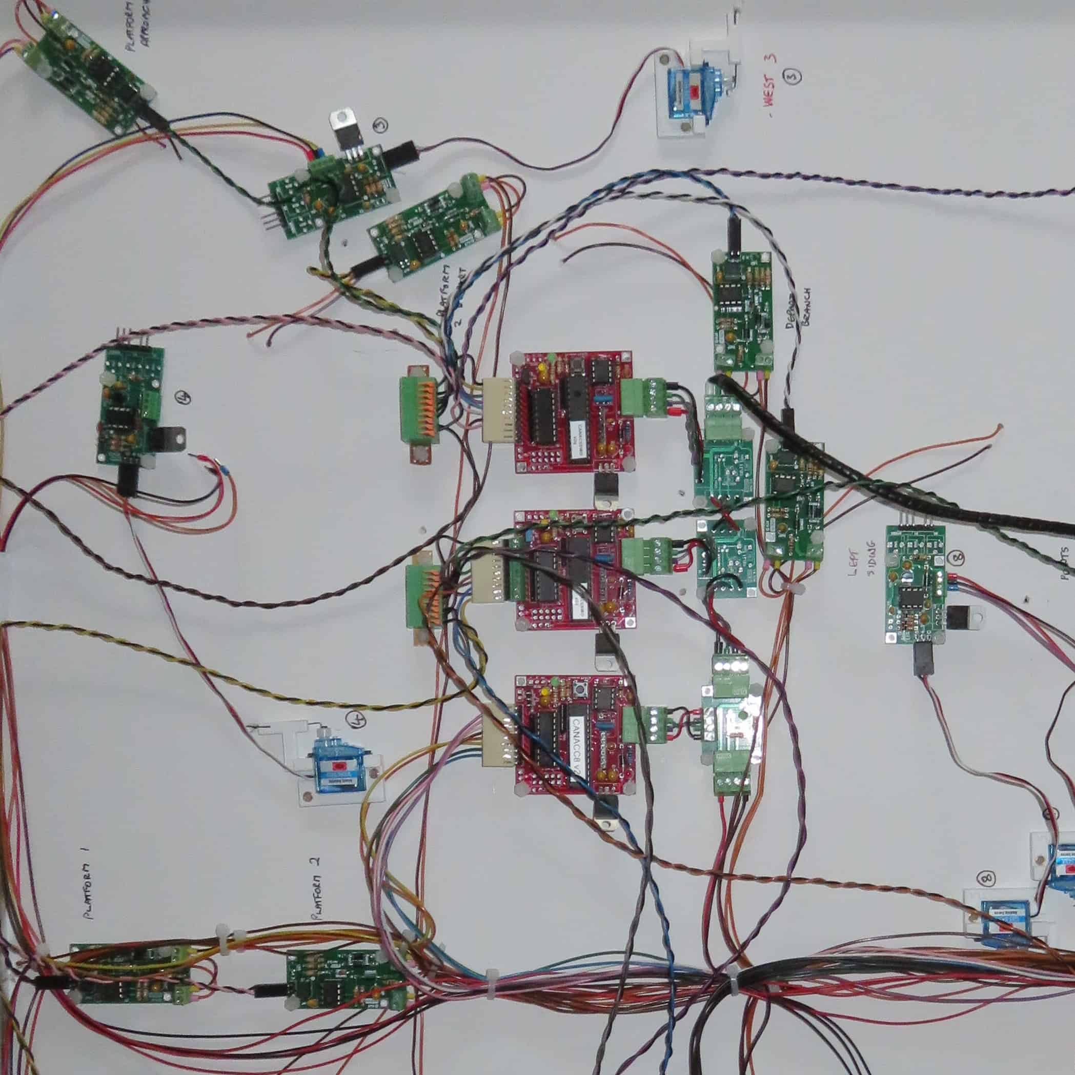
At last I have been able to put my crimper down – for now – the wiring is complete.
I’ve had problems with the space needed for the control modules that attach to the board. When they were connected with short wires, too much space was needed so I have 3D printed a chassis and mounted the modules into a compact unit.
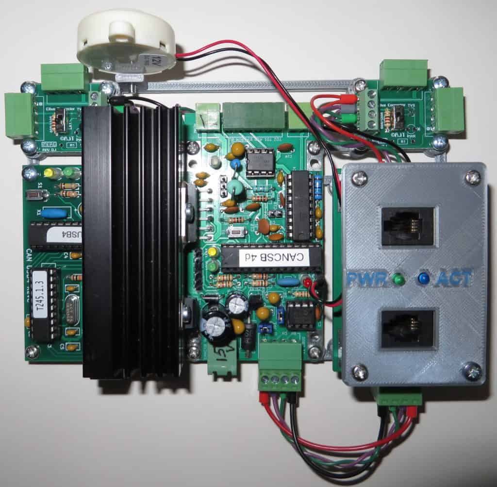
The photo shows:-
USB computer interface under the black heatsink.
- MERG DCC control unit with a 2.5 amp output stage – the buzzer gives warning of short circuits.
- Sockets for the hand help throttle along with indication lights for power and activity.
- Two sets of sockets are available to plug in the layout and any other modules.
The testing has involved running a loco around, checking that the points all work – some needed fine tuning. Each section of track has a current detector which lights a LED visible on the top of the baseboard.
The next step is to set up the Java Model Railway Interface (JMRI) software that is connected via an USB cable. A table of turnouts (points) is constructed along with a table of sensors for the current detectors.
In the JMRI software the sensors are entered along with their hardware address. Blocks are then created and linked to sensors.
A schematic of the layout in then created (JMRI calls then panels) and sections in the diagram are linked to the blocks. Now there is a linkage between the sensors under the board and sections of track on the panel.
Now as the train travels along the loop, the position is shown on the PC. When two blocks are illuminated then the front of the train is in one block and the last conducting part of the train is in the second block.
Points can also be changed just by clicking on the point that the lines diverge.