It was now clear that a new layout was required and that it should have the following characteristics:-
A1 sized foamboard on an aluminium frame
automated N-Gauge layout
block detection using DCC current sensors
3.7g servos to move the points
demonstration layout to promote discussion about electronic control.
The previous layout did not have a name but after some thinking (more wine involved) I decided on Godred’s Gap which may turn out to be part of a larger layout called Stac Tomaidh. Enthusiasts will have already spotted the allusions to the island of Sodor.
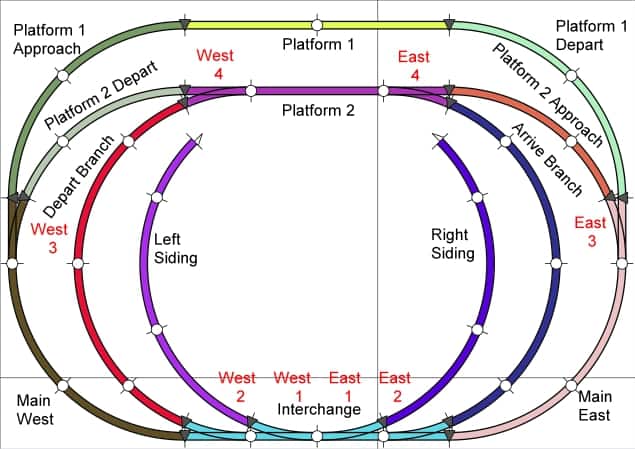
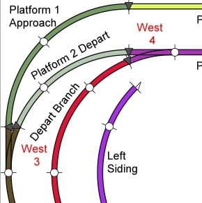
The previous layout was input into Anyrail and two sidings added. All 13 blocks were given names as well as each point.
The layouts in Anyrail can be used directly as an input to JMRI. However the Anyrail blocks are defined as JMRI blocks and not oblocks. Although the points are defined as JMRI turnouts, these still have to be deleted and re input as MERG devices.
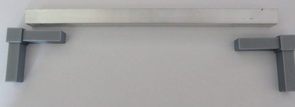
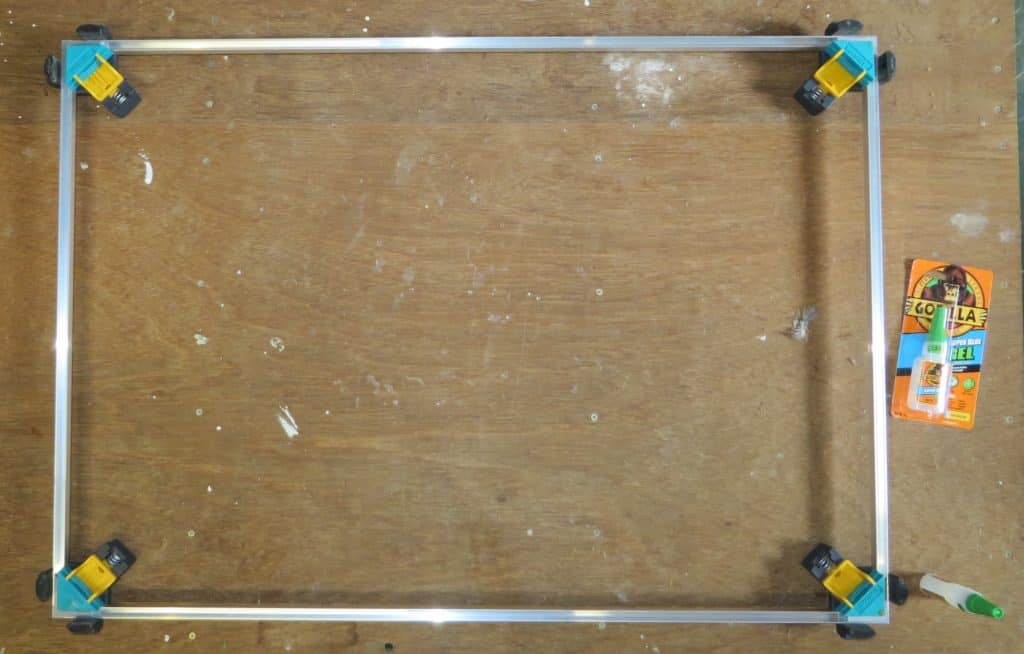
Aluminium U section was used as the chassis to give more rigidity. A 3D printer was used to create the corner joints.
A1 foamboard was glued to the chassis.
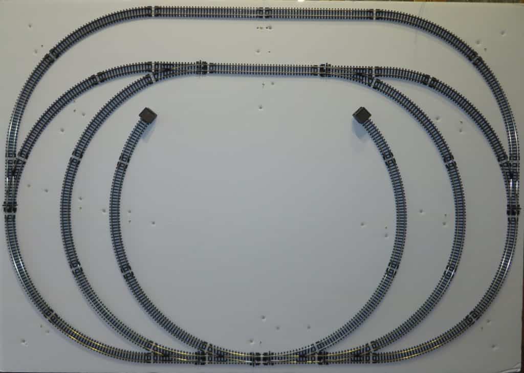
The original plan was to print out the Anyrail plan on A1 labels and stick these to the board, prior to laying the track. Unfortunately the labels have a border to allow easy peeling so the resulting labels are smaller than A1 and the positional accuracy was lost. So it was back to the ruler and pen marks to layout the track.
The track was stuck to the board using double sided sellotape. There are rolls of double sided tape from 3M that do not need a backing tape to be removed – this saves considerable amounts of time.
The dropper wires were soldered to the joining plates.
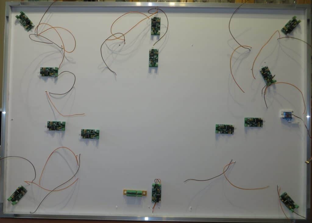
The 13 DCC current detectors were screwed to the board using nylon bolts. There is a light emitting diode (LED) on the board which illuminates when there is a loco on that section of track. The loco is detected even when it is stationary.
These LEDs were soldered to the underside of the printed circuit boards, mounted on a nylon spacer so that the LEDs are visible on the top of the board. This is going to be very helpful when testing the automation and it gives visual confirmation that the train has been detected.
Absolute block rules will apply – no train can move into a block if there is already a train in situ.
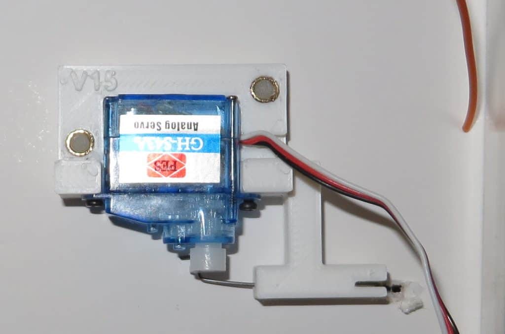
I haven’t used 3.7g servos before so I had to produce a mounting bracket to hold the servo against the underside of the board. Nylon bolts, screwed into brass inserts then hold the servo in place. Bear in mind that there is only about 10mm available under the board.
Although the prototype brackets seemed to work well, I wanted to test one of them thoroughly before installing the others.
In the meantime the eight servo driver boards have been built and tested and are waiting to be installed after the traction power cables have been completed.